Connectors, by pitch and way count.
Screw terminals, pluggable blocks, circular and rectangular shells. The current and the voltage are the maker's figures; the pitch is the figure that decides whether a part fits at all.
PCB screw terminals
rising clamp, by pitch, way count and wire range
| Pitch | Ways carried | Wire range | Rated by the maker | Wire entry | Box |
|---|---|---|---|---|---|
| 2.54 mm | 2 to 12 | 0.14 to 0.5 mm² | 6 A at 150 V | vertical | 50 pieces |
| 3.5 mm | 2 to 24 | 0.14 to 1.5 mm² | 10 A at 250 V | vertical or 45 degrees | 50 pieces |
| 3.81 mm | 2 to 24 | 0.14 to 1.5 mm² | 10 A at 300 V | vertical | 50 pieces |
| 5.0 mm | 2 to 24 | 0.2 to 2.5 mm² | 16 A at 300 V | vertical or horizontal | 50 pieces |
| 5.08 mm | 2 to 24 | 0.2 to 2.5 mm² | 16 A at 300 V | vertical or horizontal | 50 pieces |
| 7.62 mm | 2 to 12 | 0.2 to 4 mm² | 20 A at 300 V | horizontal | 25 pieces |
| 9.5 mm barrier | 2 to 12 | 0.5 to 4 mm² | 20 A at 300 V | screw from above | 25 pieces |
A screw terminal is bought by its pitch, and the pitch is the distance between the centres of two neighbouring pins. Six pitches are carried, from 2.54 mm for signal wiring up to 7.62 mm for wire to four square millimetres, plus a barrier strip on a 9.5 mm pitch for benches that want the screw on top and the wire coming in from the side. Way counts run in steps of one on every family, so a nine-way is a stock line and not a special.
The wire range is the maker's, for a single stripped conductor or a ferruled one. A rising clamp lifts a plate onto the wire as the screw is tightened, so a bare stranded wire is held over its whole cross-section; the sheet says rising clamp on every line because that is the only clamp we carry in this family. The current and voltage next to it are printed on the part or in its datasheet, and they are quoted as the maker's figure and nothing else.
Two families on the sheet, 5.0 mm and 5.08 mm, look identical on a bench and are not, and the difference is the whole subject of the section on look-alikes below. The same is true of 3.5 mm and 3.81 mm. If your board was laid out from a datasheet, the pitch on the datasheet is the pitch to order.
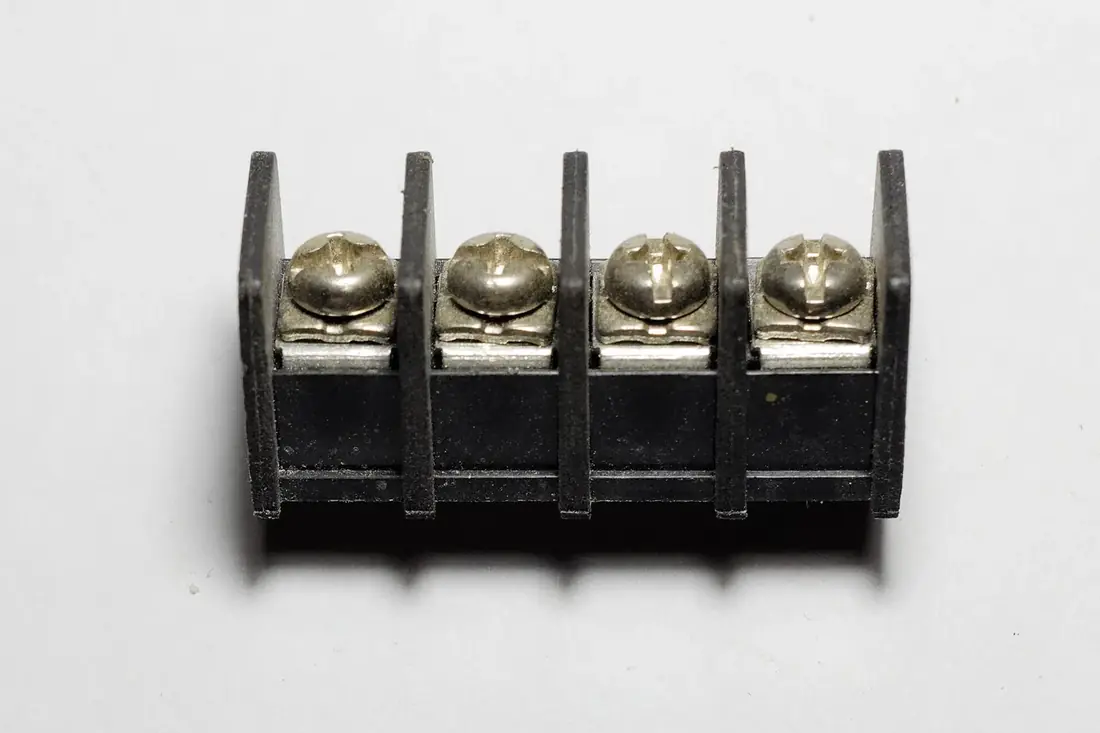
Barrier strips
The barrier strip is the odd one out in the bin: the screw sits on top, the wire is wrapped or ferruled under a washer, and moulded walls between the ways keep a stray strand from reaching its neighbour. It is the right part when a bench wants to see every connection from above with the lid off, and the wrong one when the wire enters from the front. Both entries are on the sheet; neither is better, only different.
Pluggable terminal blocks
a plug and a header, ordered as two lines
| Pitch | Ways carried | Plug clamp | Header | Rated by the maker | Box |
|---|---|---|---|---|---|
| 3.5 mm | 2 to 16 | screw or push-in | straight or right-angle, open or closed ends | 8 A at 160 V | 25 pieces |
| 3.81 mm | 2 to 16 | screw or push-in | straight or right-angle | 8 A at 300 V | 25 pieces |
| 5.08 mm | 2 to 16 | screw or push-in, with or without flange | straight or right-angle, with or without flange | 12 A at 300 V | 25 pieces |
| 7.62 mm | 2 to 12 | screw | straight or right-angle | 16 A at 300 V | 25 pieces |
A pluggable block is two parts, and a quote for one always carries two lines: the header soldered to the board and the plug that carries the wires. They are ordered in the same pitch and the same way count, and they are boxed separately because a bench that repairs equipment wants plugs by the box and headers not at all.
Headers are carried straight and right-angle, and on the 5.08 mm family with or without a flange for a screw-locked plug. Plugs are carried with a screw clamp or a push-in clamp; the push-in takes a ferruled wire without a tool and a bare wire with a small screwdriver in the release slot. The maker's current and voltage figures on the sheet are for the mated pair, and the lower of the two parts' figures always governs.
Within a family on this sheet, every plug fits every header of the same pitch and way count. Across makers, a plug of the same pitch usually enters another maker's header but the latch or the flange may not engage, and the quote says which of ours has been checked against which, when you ask.
Circular shells
M8 and M12, by contact count and coding
| Size | Contacts | Coding | Sides carried | IP mated, maker's figure | Box |
|---|---|---|---|---|---|
| M8 | 3 or 4 | A | cable plug and socket; panel socket | IP67 | 10 pieces |
| M12 | 4 or 5 | A | cable plug and socket, straight and angled; panel socket | IP67 | 10 pieces |
| M12 | 4 | D | cable plug; panel socket | IP67 | 10 pieces |
| M12 | 8 | A | cable plug and socket | IP67 | 10 pieces |
| M12 field-wireable | 4 or 5 | A | screw contacts, cable side only | IP67 | 10 pieces |
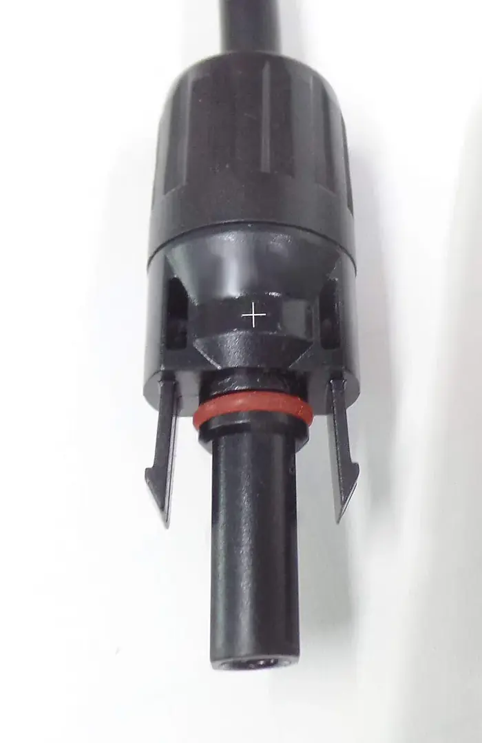
Circular connectors on the sheet are listed by thread size, contact count and coding. The coding is a key moulded into the insulator that stops an A-coded plug entering a D-coded socket; the two are carried separately and the sheet says which is which on every line. Sides are the cable plug, the cable socket and the panel socket with a rear nut, and each is its own box.
The IP figure on this family is the maker's and applies to the mated pair with the coupling nut tight; an unmated socket without its cap is open to the weather, and the caps are a separate line. Field-wireable versions with screw contacts are carried in M12 for a bench that terminates its own cable on site; the moulded versions on the other lines come from the maker as loose shells and contacts, not as leads, because we do not assemble.
Cable diameter matters as much as contact count: a field-wireable shell clamps a range of cable and a cable outside that range will not seal, whatever the IP figure says. Give the outside diameter of the cable on the part list and it goes on the quote.
Rectangular shells
D-shaped connectors and heavy-duty inserts
| Style | Ways carried | Contacts | Hood or housing | Box |
|---|---|---|---|---|
| D-shaped, standard density | 9, 15, 25 or 37 | solder cup, machined or stamped | metal hood, plastic hood, panel mount | 10 |
| D-shaped, high density | 15, 26 or 44 | solder cup | metal hood | 10 |
| Heavy-duty inserts | 6, 10, 16 or 24 | screw or crimp | top-entry and side-entry hoods; bulkhead and surface housings; single or double lever | 5 |
| Insert accessories | as above | crimp contacts by wire size | coding pins, locking levers, gland plates | 50 |
Two very different families share this bin because both are rectangular and both come apart into shells, contacts and hoods. The D-shaped connectors are listed by way count and density, with solder-cup contacts as stock and crimp as ordered-in; hoods are metal or plastic and a panel-mount version with a threaded stand-off is carried in the standard-density sizes.
The heavy-duty inserts are the panel builder's line: an insert with screw or crimp contacts, a hood on the cable side, a housing on the panel side, and a lever or two to lock them. Every one of those is a separate line on the quote, and a complete connector is five or six lines. We list them that way on purpose, because a bench that has the hoods and only needs inserts should not be paying for hoods.
Contacts are sold by the box in the wire size they crimp to, and they do not cross between the two families. The maker's current figure is per contact and drops as the insert fills, exactly as the datasheet shows it, and we quote the datasheet figure without rounding it up.
How to read a part number
four segments, left to right, hyphen between each
| Segment | Meaning | Values used |
|---|---|---|
| TB | family | TB screw terminal · PL pluggable plug · PH pluggable header · CS circular shell · RS rectangular shell |
| 508 | pitch in hundredths of a millimetre | 254 · 350 · 381 · 500 · 508 · 762, with 950 kept for barrier strips |
| 06 | way count | 02 to 24, always two digits |
| V | entry or form | V vertical · H horizontal · A angled 45 degrees · R right-angle header · S straight header · F flanged |
Every connector line on a Micronoxs quote carries a code built from four segments, and the code is the description compressed: TB-508-06-V is a screw terminal block on a 5.08 mm pitch, six ways, vertical wire entry. PL-381-08-P and PH-381-08-R are a pluggable plug with push-in clamp and its right-angle header, both on 3.81 mm and both eight ways.
The code is ours and travels on the quote and the packing list. The maker's own number is written beside it on every line, so a purchasing office can check one against the other and a repair bench can find the datasheet.
When you send a maker's number we do not carry, the cross-reference comes back as a Micronoxs code plus a list of every measurement that differs. Pitch and way count are checked first, then wire range, then rated current and voltage, then the physical form; a match on the first two with a difference on the third is reported as exactly that, not as an equivalent.
Look-alikes that are not the same part
the differences a bench cannot see and a board can
5.0 mm against 5.08 mm. Side by side, a bench cannot tell them apart; a board can. A twelve-way block has eleven gaps between its pins, and eleven times the 0.08 mm difference is 0.88 mm. The end pins land almost a millimetre off the holes, and the block either will not seat or seats bent. Order the pitch printed on the layout, not the one that looks right.
3.5 mm against 3.81 mm. The same arithmetic with a bigger step: eleven gaps at 0.31 mm is 3.41 mm across a twelve-way, which is very nearly a whole pitch. On a two-way block it seats; on anything longer it does not.
Plug against header, across makers. Two makers' 5.08 mm plugs will usually enter each other's headers. Their latches, flanges and coding tabs are not standardised, so a locked connection on one maker's pair may be a loose one on the mix. Within one family on our sheet, every plug fits every header of the same pitch and way count; that statement stops at the family.
A-coded against D-coded M12. Same thread, same nut, same four contacts; the key in the insulator is in a different place and the pair will not mate. The sheet carries both and marks each line.
Standard against high density D-shaped. A high-density 15-way sits in the shell size of a standard 9-way. Hoods fit by shell size, not by way count, and the hood line on the quote names the shell size for that reason.
Send the layout's pitch and way count and the quote comes back with the family that fits. Ask for a price on a part.